I'm working on building a breadboard general-purpose computer as an exercise in learning electronics.
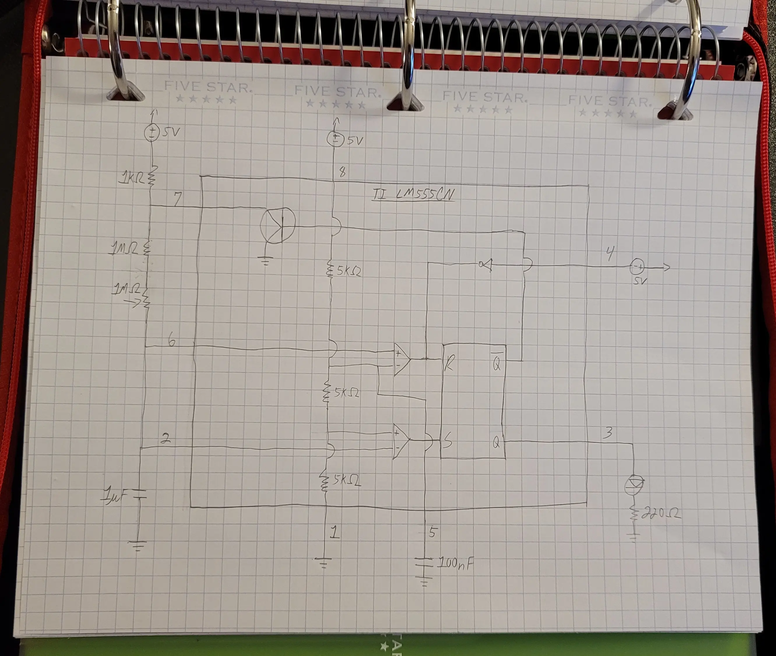
All computers begin with a timer. So, this is my Texas Instruments LM555CN timer with a potentiometer to control the timing rate.
Here's the circuit diagram.

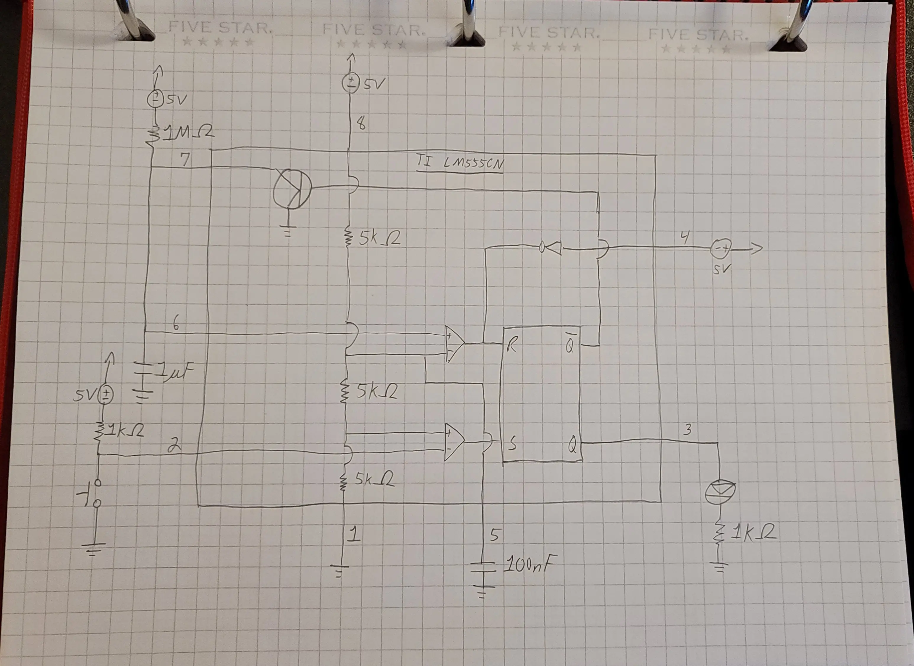
I will also want to be able to step through instructions being executed; so, I have a second, monostable, 555 timer with a button to activate a clock tick.
Here's the circuit diagram.

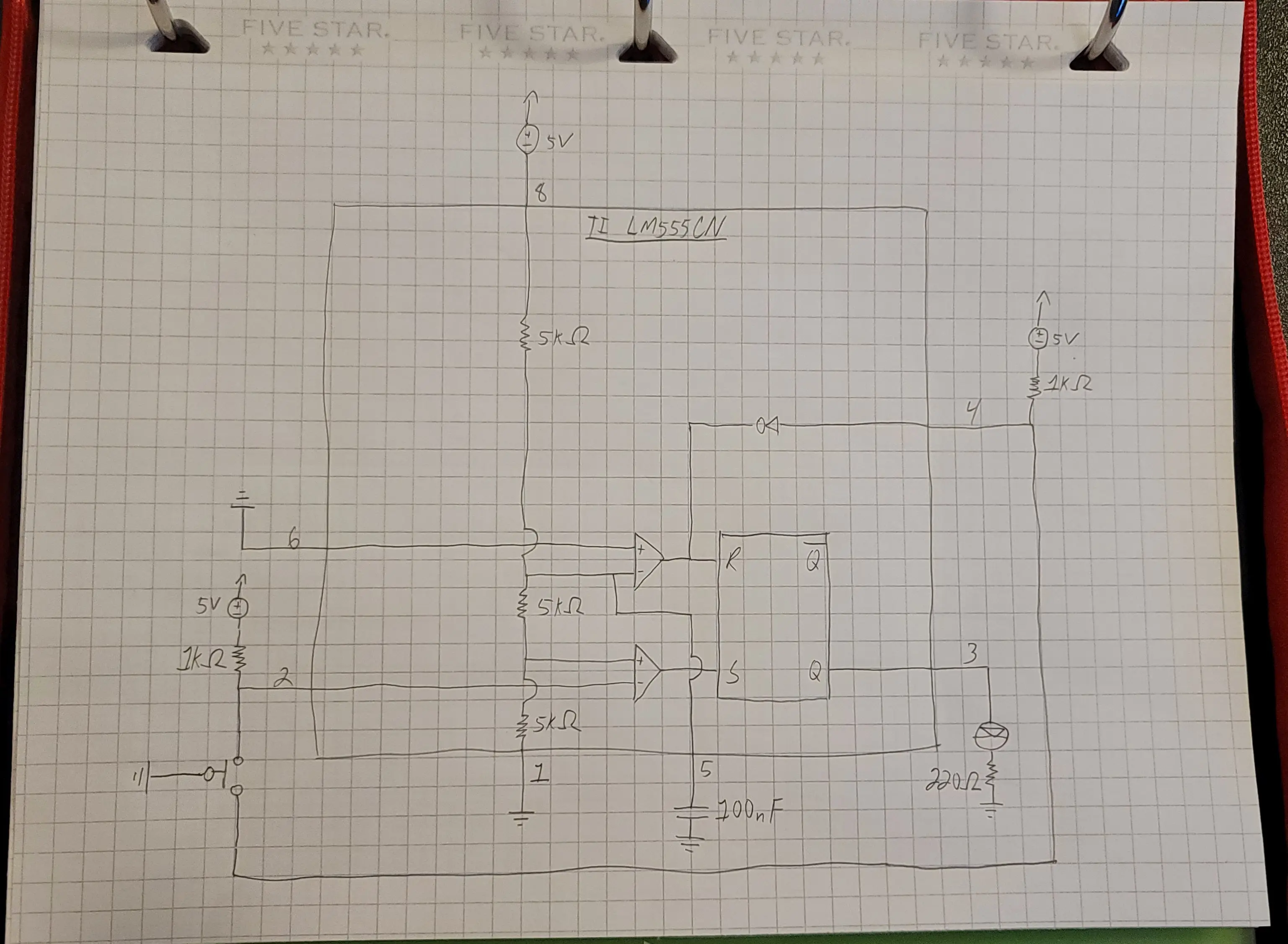
In order to switch between the two timers, I have a third, bistable, 555 timer where I'm leveraging its flip-flop as a debounce circuit for a switch. This will ultimately connect the previous two timers and switch between them.
Here's the circuit diagram.

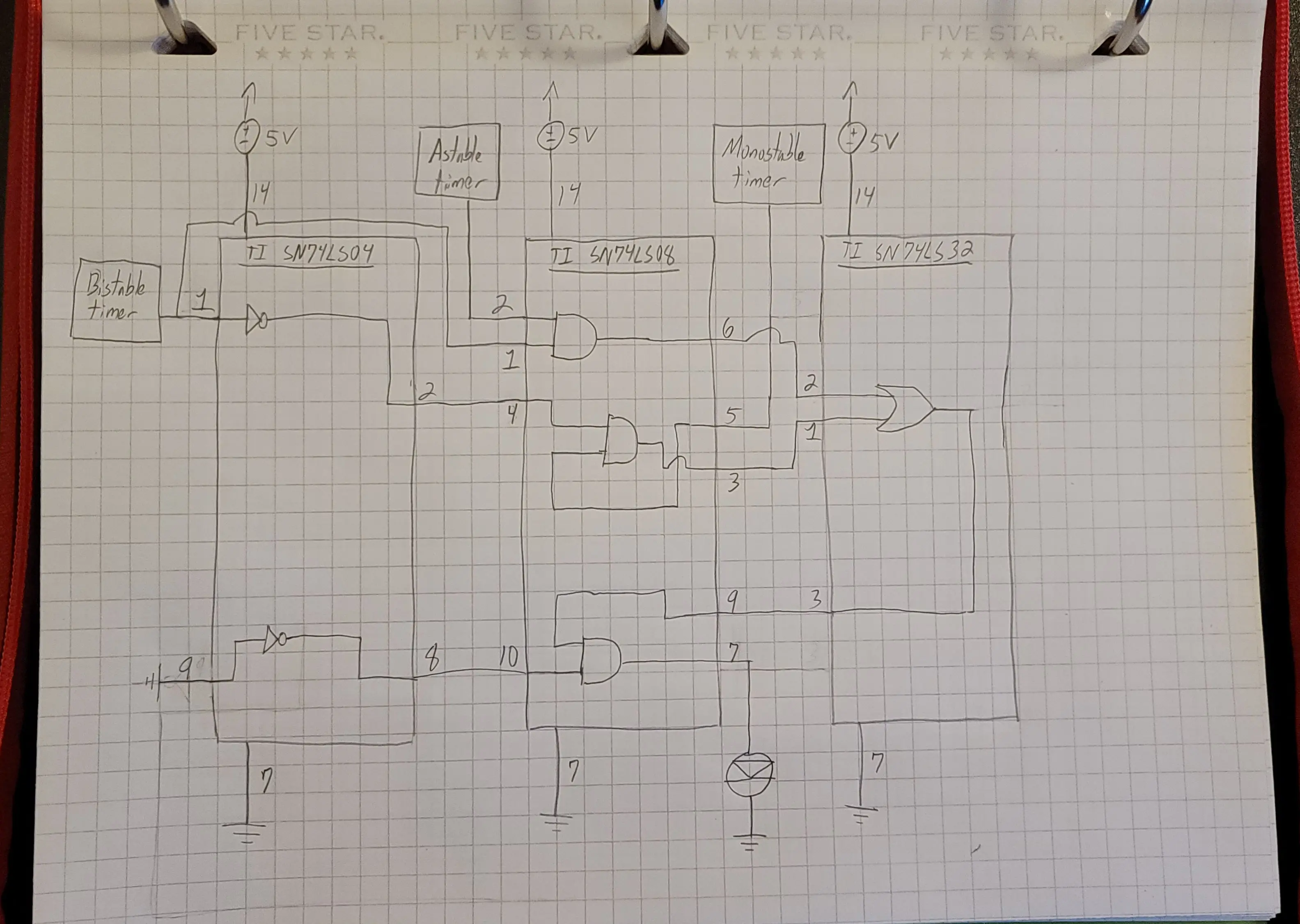
Finally, I used three more TI packages for logic gates to hook it all up. The SN74LS04 is a package of inverters. The SN74LS08 is a package of AND gates. The SN74LS32 is a package of OR gates.
Now, the switch on the bistable circuit will switch between the astable clock and the monostable clock. So, I can run the computer like normal (astable) or step through code (monostable). There's also a halt line that will stop the clock altogether.
Here's the circuit diagram.
